
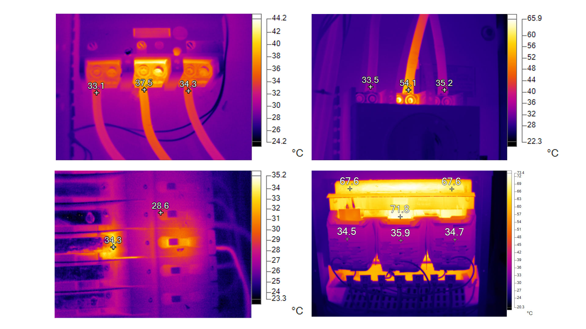
Thermographers use infrared (IR) cameras to capture thermal images of electrical components as part of routine maintenance programs. These images reveal abnormal heat patterns and localized hot spots that may indicate underlying deficiencies requiring further investigation before they develop into a fault.
One common evaluation technique is the Delta T method, which measures the temperature difference between a suspected overheating component and a reference point. The reference may be the ambient air temperature or a comparable component operating under similar load and environmental conditions.
This temperature difference, referred to as Delta T, helps determine the severity of the overheating condition. Generally, a higher Delta T value corresponds to a more serious issue and an increased risk of component degradation or failure.
Shortcomings of The Delta T Method
The Delta T method has long been used for routine maintenance inspections, but it has some important limitations. One issue is that it does not account for changes in electrical load. If the equipment is not operating under normal or full load during an inspection, the temperature readings may be misleading.
The method also assumes that the reference temperature is accurate and stable, which is not always true. Changes in ambient conditions or differences in the reference component can affect the results. In addition, factors such as surface emissivity and heat reflections from nearby objects can influence infrared camera readings, potentially leading to incorrect conclusions.
These factors have a major impact on equipment operating temperature. The electrical load determines how much current flows through the equipment, which directly affects its temperature. In general, higher loads produce higher temperatures.
As a result, fixed temperature limits do not always reflect real-world operating conditions. To be meaningful, these limits need to be adjusted based on the surrounding temperature and the actual load on the equipment at the time of inspection.
Correcting IR Readings for Load and Ambient Temperature
Several IEEE standards provide a way to adjust temperature readings so they better reflect real operating conditions. As described by Paul Gill in Electrical Power Equipment Maintenance and Testing, this correction uses a simple formula to account for differences in electrical load and ambient temperature:
Ttc = (Trt − Tra) × (Im / Ir)ⁿ + Tma
In plain terms, the formula adjusts the measured temperature by factoring in how much current the equipment is actually carrying compared to its normal load, and then adds the surrounding air temperature. This helps produce a more accurate temperature value that can be used to better judge the true severity of an overheating condition.
Let’s breakdown each part:
- Ttc is the highest safe operating temperature for the equipment under inspection after adjusting for the actual electrical load and the surrounding air temperature.
- Trt is the maximum temperature the equipment is designed to handle. This value is typically listed on the equipment nameplate or in the manufacturer’s documentation.
- Tra is the ambient temperature the equipment was originally rated at. This information is also found on the nameplate or in the manufacturer’s literature.
- Im is the actual electrical current flowing through the equipment at the time of the inspection. It must be measured safely using a calibrated current meter.
- Ir is the maximum continuous current the equipment is rated for. This value is usually clearly marked on the equipment nameplate.
- Tma is the actual ambient (surrounding) temperature at the time of the inspection, measured using a calibrated thermo-hygrometer.
- n is a factor that represents how temperature increases as load increases. It typically ranges from 1.6 to 2.0. The applicable standards should be consulted for the correct value, though an average value of 1.8 is noted in Paul Gill’s book.
Calculating Total Corrected Temperature
Although the formula may look complex, the corrected temperature is easy to calculate when broken into steps. All you need is the applicable temperature standard, the ambient temperature, the equipment’s rated load, and the actual measured load. Let’s walk through the process.
1. Rated Temperature
First, determine which temperature standard applies to the equipment being inspected. The correct standard depends on the type of equipment and the specific component involved.
For example, temperature limits for a low-voltage circuit breaker terminal connection to a bus or cable are defined in ANSI/IEEE C37.13, Standard for Low-Voltage AC Power Circuit Breakers Used in Enclosures.
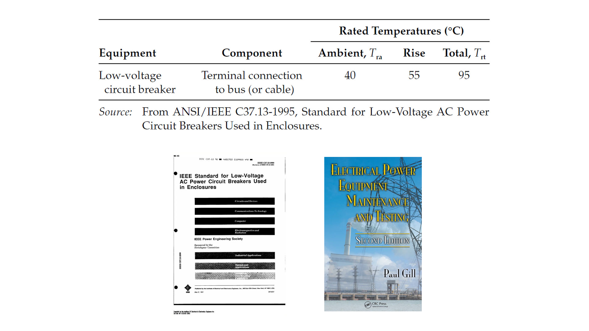
Using the numbers from this standard, we subtract the total rated temperature of 95°C from the rated ambient temperature of 40°C to get 55°C.
2. Load Conditions
Next, determine the equipment’s maximum rated current and the actual current at the time of inspection. For example, a breaker rated for 100 A might only be carrying 30 A during the inspection.
In the formula, divide the measured current by the maximum rated current and then raise the result to the chosen exponent. In this example, Gill uses the maximum exponent of 2.
(30 / 100)² = (0.3)² = (0.09)
3. Measured Ambient Temperature
Finally, measure the surrounding air temperature using a thermo-hygrometer. In the example, we use a standard baseline of 20 °C for demonstration purposes.
Related: Optimizing Infrared Scans: 5 Key Elements for Comprehensive Reporting
4. Result
After entering the values into the formula, you get the total corrected temperature (Ttc). This is the maximum temperature the equipment can safely reach under the current conditions. It accounts for the actual ambient temperature and is adjusted downward if the equipment is operating below its rated load.
Ttc = (55) (0.09) + 20 = (4.95) + 20 = 24.95°C
Comparing Measured Temperature to Max Limit
The thermographer then compares the temperature they measured with the infrared equipment to the corrected temperature limit.
- If the measured temperature is higher than Ttc, the equipment is too hot and does not meet the standard.
- If the measured temperature is lower than Ttc, the equipment temperature is within an acceptable range.
In this case, the thermographer measured 31 °C at the terminal lug. The total corrected temperature (Ttc) is 24.95 °C.
Since 31 °C is higher than 24.95 °C, the breaker is overheating and does not meet the standard. The terminal is 6.05 °C over the temperature limit.
This indicates a problem that could worsen if the electrical load increases or if the surrounding temperature rises.
Emissivity and Camera Accuracy
Accurate temperature measurements are essential so the results can be properly compared to the corrected temperature limit. Different materials emit infrared radiation differently, so the thermographer must adjust the camera for the emissivity of the surface being measured.
It’s important to account for reflections from nearby hot or cold surfaces, which can affect the infrared camera readings. Knowledge of surface emissivity values and the proper image adjustments ensure the temperature measurements are reliable.
Standards-Based vs. Delta T, Which is Better?
If the other two phases of the breaker in our example are at the surrounding temperature (20 °C), the Delta T method would calculate the temperature difference as:
31 − 20 = 11 °C
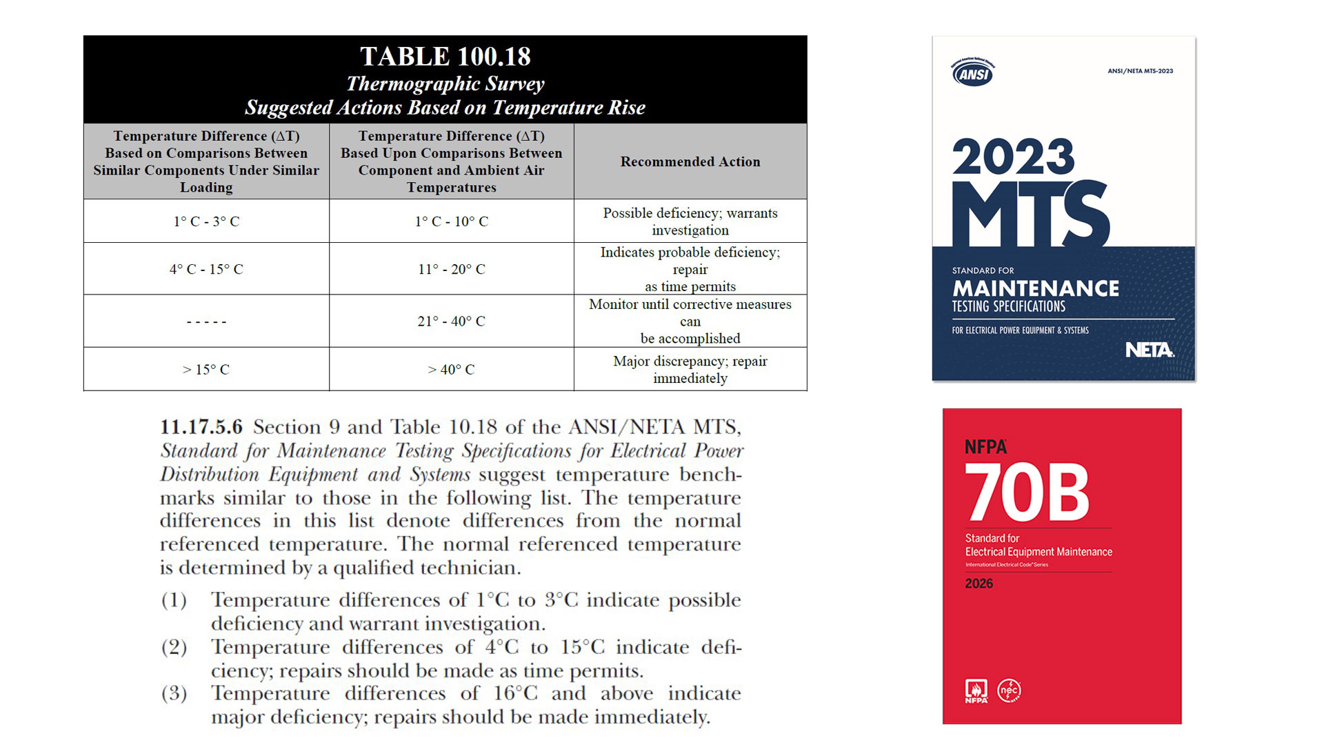
According to NETA-MTS Table 100.18 Suggested Actions Based on Temperature Rise, this would be considered a low-to-moderate problem that can be repaired as time permits. However, the standards-based system, which adjusts for actual ambient temperature and load, shows that the equipment is already above its safe limit.
When comparing the two methods across many similar cases, the standards-based approach is generally more precise. It flags potential problems earlier than the Delta T method and provides a more accurate assessment of thermographic data. The trade-off is that it takes more time to collect the required information.
Conclusion
Infrared thermography is a powerful tool for spotting overheating electrical components, and both the Delta T method and standards-based approach are used to assess risk.
The Delta T method is simpler, measuring the temperature difference between a component and a reference point, but it has limitations. It doesn’t account for changes in electrical load, ambient temperature, or surface characteristics, which can lead to inaccurate readings.
By contrast, the standards-based approach adjusts for these factors using formulas that consider the actual load, surrounding temperature, and equipment ratings, giving a more precise picture of whether a component is operating safely.
While the standards-based method takes more time and requires careful measurement, it tends to identify potential problems earlier than the Delta T method, making it a more reliable tool for preventive maintenance.
Applying this approach correctly—including accounting for emissivity, reflections, and measurement accuracy—helps keep electrical equipment within safe operating limits and supports more effective maintenance decisions.
![]() With 20 years of experience in power systems testing and maintenance, I am a seasoned professional dedicated to enhancing operational efficiency. I excel in improving processes, systems, tools, research, training, and technology implementation. Contact me to see how we can keep your systems running at peak performance.
With 20 years of experience in power systems testing and maintenance, I am a seasoned professional dedicated to enhancing operational efficiency. I excel in improving processes, systems, tools, research, training, and technology implementation. Contact me to see how we can keep your systems running at peak performance.
You may also like...
- Data security tips for testing agencies and the clients they serve
- SF6 Gas Alternatives for a Sustainable Energy Future
- Infrared Insights: The Path to Preventing Electrical Failure with IR Technology
- Next-Generation Substation Technology: Centralized Protection and Control
- Why insulation resistance trending may be your best predictor of electrical failure
