Personal protective grounding provides shock protection for technicians working on de-energized equipment. If done correctly, it is by far the most effective means of protection from electrical shock.
When a circuit has been properly grounded for the protection of workers — and it accidentally becomes energized — the voltage on the system sags to near zero. However, the grounding cables cannot carry these massive amounts of current for more than a fraction of a second.
Therefore, the technicians’ lives depend upon the device that protects the circuit (to de-energize it) before the grounding cables melt open and voltage levels return to unsafe levels.
Part 1: Selection of Personal Protective Grounding Equipment
Grounding cables need to be carefully selected to ensure the protection of technicians. Choosing the wrong size of cable, or wrong the style of clamp, can prove to be deadly. Using this four step process can help you make the best selection for the application at hand.
Step 1. Determine Maximum Available Fault Current at Worksite
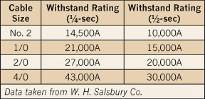
Both the current magnitude and duration (clearing) time must be established to determine cable size (ampacity) and allowable cable length. Determine the maximum fault current of the supply transformer with the following formula:
FC = (VA / L-L Voltage x 1.732) / Impedance
Example: Calculate the maximum fault current for a transformer rated 13.8kV-480Y/277V 1000kVA 5.75%Z
FC = (1,000,000 / 480 * 1.732) / 0.0575 = 20,919 A
Step 2. Size the Cables
The primary considerations when selecting grounding cables is their withstand rating for fault current and their length. Choose the appropriate cable ampacity based on the calculated maximum fault current and chosen clearing time at the worksite. The conductors must be made of multi-stranded copper and can be no smaller than 2 AWG.
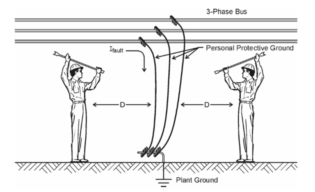
Personal protective grounds should be of adequate length for the job, but without excessive cable that must be laid out of the way. When any circuit conducts high current, strong magnetic fields develop that cause the cables to try to whip violently in response to the attractive or repulsive magnetic fields between the phase conductors. This whipping motion can cause the grounding cables to move back and forth several times in 1 sec, which could result in severe physical trauma to anyone in the vicinity of the cables.
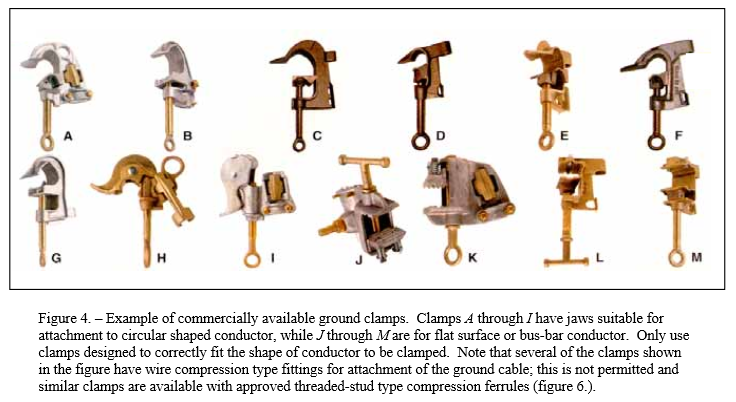
Step 3. Clamp Selection
With so many commercially available ground clamp options, it’s important to pick the clamps with jaws suitable for your specific application. Only use clamps designed to correctly fit the shape of the conductor to be clamped. Some jaws are designed for circular conductors, while others are designed for a flat surface or bus-bar conductor.
Step 4. Inspect the Cables Inspect Cable Assemblies
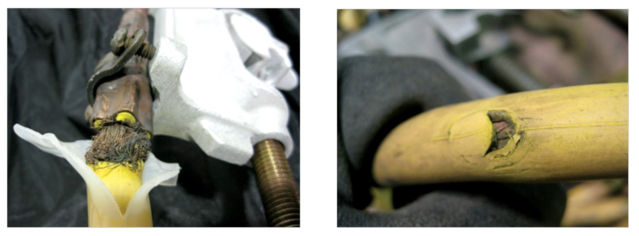
Ground cable assemblies should be visually and mechanically inspected before each use. Cables should be carefully examined to detect broken strands, corrosion, and other physical damage to the cable.
Serrated jaws should be replaced when they become worn. Clamp bolt threads should be checked for wear and smoothness of mechanical operation. When in doubt, electrical resistance tests (DLRO) can be performed to check electrical integrity of the cable.
Part 2: PPE Selection for Personal Protective Grounding
Electric shock and the potential for arc flash are the two main hazards of applying personal protective grounds. Reference NFPA 70B Table 13.7(C)(15)(a) for the appropriate selection of PPE.
For example, the application of temporary protective grounding equipment, after voltage test, on Metal clad switchgear 1kV-38kV requires a Hazard/Risk Category 4 and properly rated rubber insulating gloves.
Part 3: Protective Grounding Installation and Removal Procedure
Step 1. De-energize Power Source, Lock & Tag Equipment
Follow the normal lockout/tagout (LOTO) procedures found in 29 CFR 1910.147 and 29 CFR 1910.269.
For high voltage systems, it is a requirement to get a “visual open” in the circuit, so that the technician can visualize an air-gap in the switches used to isolate the circuit. This can be achieved either by opening a solid-blade switch that can be visualized, “racking out” a circuit breaker or any other means that positively separates the electrical contacts in an energy isolating device.
Step 2. Verify a De-energized State
Always remember that a circuit is to be treated as energized until properly locked out and tested for the absence of voltage. Perform a three-point test (live-dead-live) using a proximity voltage sensing device such as a glow stick or tic tracer with a voltage rating that is appropriate for the application.
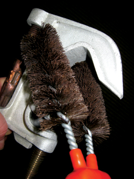
Step 3. Clean the Grounding Connection Points
To ensure the lowest possible exposure voltage, grounding connections must be clean. Surfaces of grounding hardware may be corroded or contaminated and should be cleaned by wire brushing before the grounding clamps are installed.
Step 4. Apply Ground-end clamps
The clamp must be tightened securely to provide a low resistance electrical bond and a secure mechanical connection. Ground-end clamps should be connected to a grounding point as close as practical to the location where workers are likely to simultaneously contact grounded objects (metal equipment enclosures, circuit breaker and transformer tanks, etc.) and exposed parts of temporary grounded equipment at the worksite.
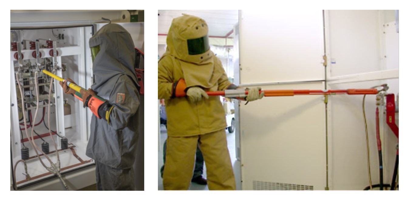
Step 5. Circuit-end (working end) clamps
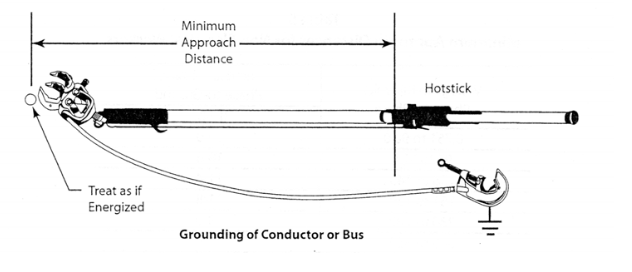
Apply the circuit-end of ground cable assemblies after the ground-end clamps are connected. The circuit or working end clamps should always be connected and disconnected by means of hot sticks of adequate length to meet minimum approach distances when possible.
Voltage rated insulated gloves should be used whether applying grounds with a hot stick or by hand. Remember, the bus is considered energized from a safety standpoint until properly grounded.
Grounds must be installed close to the technicians but not so close as to be endangered by whipping of the cables due to high currents.
Grounds should be installed within sight of the technicians. Installed cables should not be twisted, coiled, or wound around objects.
Step 6. Barricade
Place barricades as necessary to protect installed grounds from physical disturbance or accidental removal. If equipment cabinets must be closed with grounds installed inside, the cabinets should be clearly tagged on the outside indicating GROUNDS INSTALLED – DO NOT ENERGIZE.
Tags may also be attached to ground cables to track that all installed grounds have been removed before the worksite equipment is re-energized.
Step 7. Removal of Protective Grounds
Protective grounds should be removed in reverse order from installation. The circuit-end clamps should be disconnected in succession, starting first with the farthest ground cable or circuit, in a manner that creates a safe exposure (minimum approach distance) to ungrounded circuit conductors as the grounds are removed.
Ground-end clamps must be disconnected after the circuit-end clamps have been removed. Account for all protective grounds to ensure they have been removed before re-energizing the line or equipment.
References
Personal Protective Grounding for Electric Power Facilities and Power Lines
Basics of Personal Protective Grounding
Which one of these ground sets failed?
Applying Personal Protective Grounds – OHS
Grounding Encyclopedia – Hubble Power Systems
![]() With 20 years of experience in power systems testing and maintenance, I am a seasoned professional dedicated to enhancing operational efficiency. I excel in improving processes, systems, tools, research, training, and technology implementation. Contact me to see how we can keep your systems running at peak performance.
With 20 years of experience in power systems testing and maintenance, I am a seasoned professional dedicated to enhancing operational efficiency. I excel in improving processes, systems, tools, research, training, and technology implementation. Contact me to see how we can keep your systems running at peak performance.
You may also like...
- When Replacement Takes Years: Proven Strategies for Transformer Longevity
- Teaching ChatGPT to Analyze Test Results
- The Lifecycle of Protective Relays: Aging and Maintenance Insights
- How Accurate Test Results Drive Smarter Electrical Operations
- Infrared Insights: The Path to Preventing Electrical Failure with IR Technology