Infrared cameras serve as indispensable tools in electrical inspections, allowing for non-contact temperature measurements, which can help identify hot spots in distribution systems that may indicate loose connections, overloaded circuits, or other potential issues.
Advancements in digital imaging make it possible for easy point-and-shoot operation. However, infrared cameras are not devices meant for a “set and forget” approach.
In order to properly develop and interpret a thermographic inspection, it’s important to consider several often-overlooked factors. Let’s explore five essential elements that can significantly enhance the accuracy and insight of infrared reports.
1. Ambient Temperature and Wind Speed
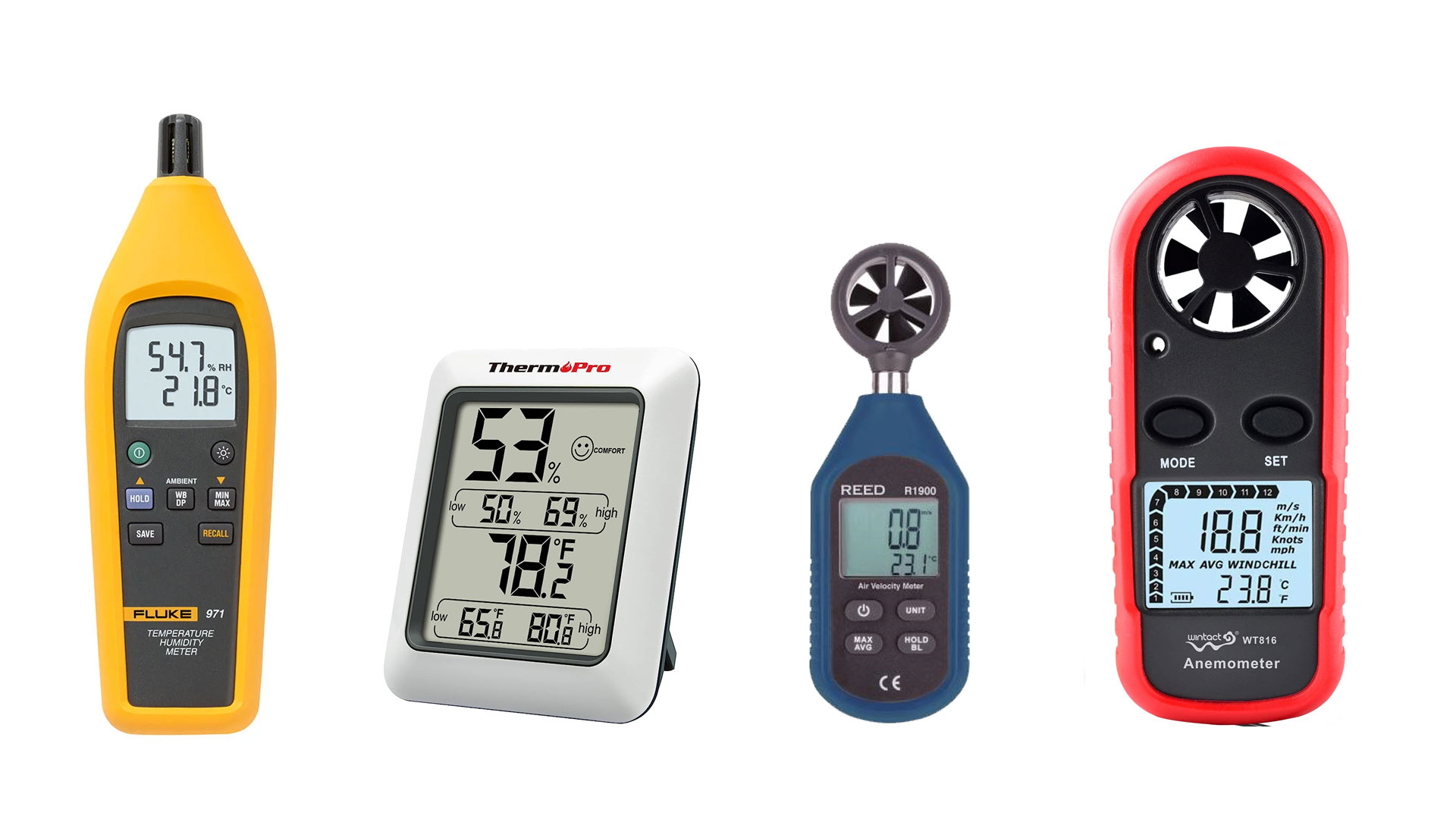
Measuring the difference between a hot spot and ambient temperature can be helpful in determining the severity of a problem when there is no similar equipment available for comparison. Ambient temperature and humidity should be documented in an infrared report and can be obtained by keeping a handheld thermometer nearby.
Air movement can have an effect on thermal signatures. When performing infrared inspections, you need to be aware of forced convection from sources such as wind, fans, and pumps because it will affect the target temperature.
For outdoor inspections, it can be useful to note the weather conditions in your report. Descriptive wind conditions (breezy, gusty, etc.) are sufficient when an anemometer is unavailable.
When scanning indoors, be mindful of any air handler units that could be close by. Equipment in climate-controlled areas may not exhibit problems as clearly as they would at room temperature, so it’s important to document the local environment as well.
2. Load Conditions
Measuring the equipment load must be performed by a qualified person and infrared technicians do not always meet this criteria. For this reason, load readings often get left out of reports.
Industry standards recommend a minimum load of 40% when performing infrared scans to allow for sufficient heating of the conductors. Without system load information in the report, it is not possible to know how effective the inspection was.
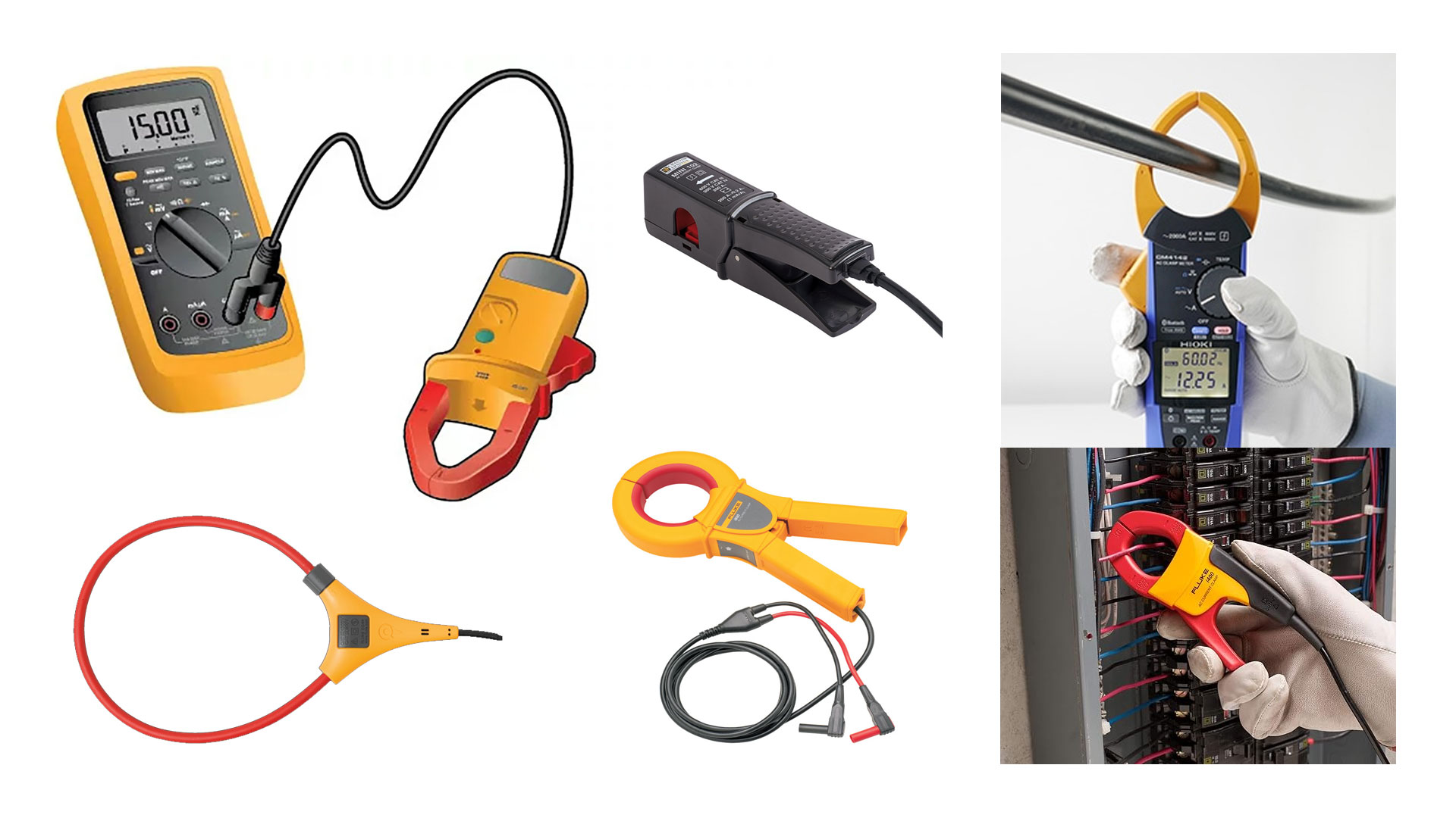
Load measurements can easily be obtained from equipment metering. On switchgear, for example, this can be done at the panel meter or individual trip unit displays.
A digital multi-meter with a current clamp can be used on small distribution panels by qualified individuals when equipment metering is unavailable. The load values are typically obtained at the incoming cables of the equipment.
3. Equipment Ratings
Electrical equipment to be inspected should be clearly identified in the report by location and asset name. This will typically include the building floor, room number, and equipment identification tag.
It is also helpful to document the voltage class, along with the maximum ampere rating of the equipment, to compare with the measured load conditions in the report. This information can be gathered simply by reading the nameplate on the front of the equipment.
4. Emissivity Values
Highly reflective objects do not emit thermal radiation very well. They reflect infrared light just like visible light, so you can easily get false readings. This is why a shiny lug can sometimes appear hotter than cable insulation because you are seeing the reflection of other heat sources on the lug.
The dull, non-reflective insulation provides a better reading. Bus bar is a good example of a low-emissivity object, as you can see the difference when scanning insulated versus non-insulated switchgear.
You can often see your own body heat if you stand directly in front of a shiny object you are inspecting, such as the inside of an enclosure. With that said, it’s still possible to see loose connections on shiny bus, but it requires a different technique.
Infrared cameras have an emissivity value that can be adjusted to compensate for reflection. When performing electrical inspections, however, this typically does not need to be adjusted for comparison between similar objects.
It is important to be mindful of emissivity and understand when it could affect your readings. If reflections are a problem, try changing the view angle of the camera by standing off to the side.
5. Reference Temperature
It can be helpful to include a temperature point on your thermal images at ambient temperature. This may be a physical support, object not under load, or part of the enclosure.
The temperature point is not an exact value, but it can give you a “background temperature” that can be used to compare against areas of concern. Just be mindful that any comparisons with this point should be made between objects with similar emissivity.
Summary
Conducting thorough infrared inspections of electrical systems requires careful consideration of various factors such as ambient temperature, wind speed, and emissivity values. It’s essential to accurately identify and document equipment locations, asset names, and relevant load information to ensure comprehensive reporting.
Understanding the impact of emissivity on thermal readings and employing techniques to mitigate reflections can enhance the accuracy of inspections. Furthermore, including temperature points at ambient levels in thermal images provides valuable context for comparison, although it’s important to ensure similarity in emissivity when making comparisons.
By adhering to industry standards and best practices, technicians can effectively leverage infrared technology to detect potential issues in electrical systems and prevent costly failures.
![]() With over 20 years of experience in power systems testing and maintenance, I am a seasoned professional dedicated to enhancing operational efficiency. I excel in improving processes, systems, tools, research, training, and technology implementation. Contact me to see how we can keep your systems running at peak performance.
With over 20 years of experience in power systems testing and maintenance, I am a seasoned professional dedicated to enhancing operational efficiency. I excel in improving processes, systems, tools, research, training, and technology implementation. Contact me to see how we can keep your systems running at peak performance.
You may also like...
- Spotting Electrical Problems Before They Become Serious: A Standards-Based Approach
- Why insulation resistance trending may be your best predictor of electrical failure
- Protecting Critical Electrical Infrastructure from Attack
- Strategies for Reducing Load Interruptions During Electrical Maintenance
- Enhancing Reliability: The Role of Overhead Power Line Monitoring in Preventing Failures